Introduction
In this tutorial, I’ve used information from http://www.tolaemon.com/nss/ as well as my own experience for testing.
You’ll not only know how to assemble & flash SwinSIDs, but how to do it almost automatically.
SwinSID is a microcontroller-based clone of the SID, the audio chip used in nearly all 8-bit Commodore computers in the 80s, and later in some chiptune synths like SIDStation. The original SID ( Sound Interface Device) was designed by the engineer Robert Yannes and produced by MOS Technology under the names MOS 6581 and MOS 8580 from the early 80’s to the early 90s. Despite the production of the original SIDs stopped years ago, you still can find spare units of unknown origin on some internet sales sites, but they are very expensive and usually have some of their parts damaged ( it is not strange to find units with malfunctioning filters or oscillators ).
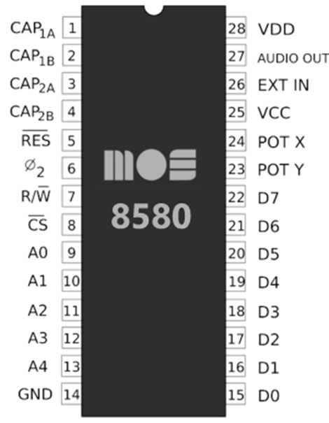
Pinout of SID(and SwinSID too):
Ordering boards
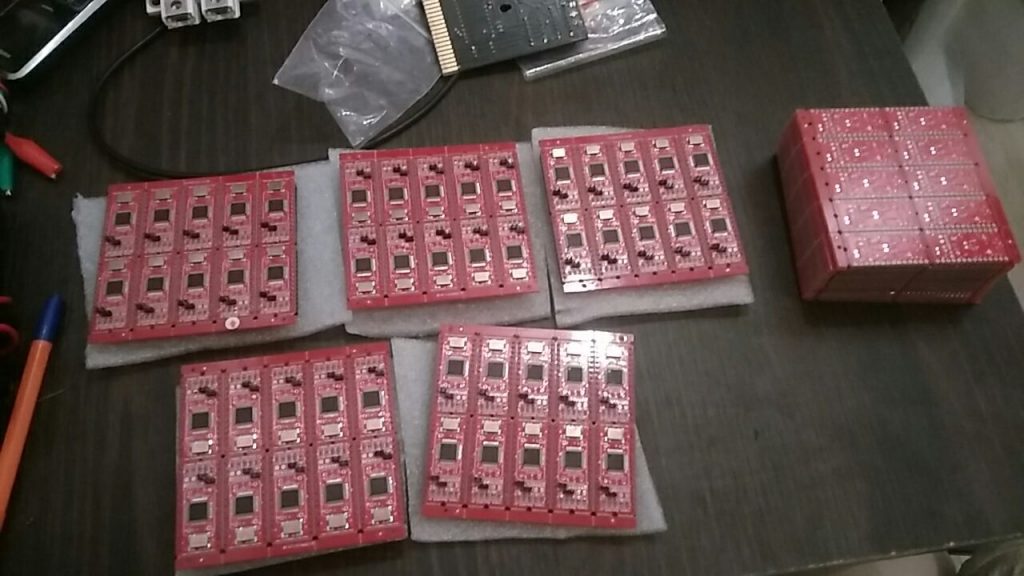
Here we’ll order boards that they will become partly(or fully) assembled.
To order fully assembled boards I do prefer PCBWay (use https://pcbway.com/g/Cc53D7), however you can use any other manufacturer.
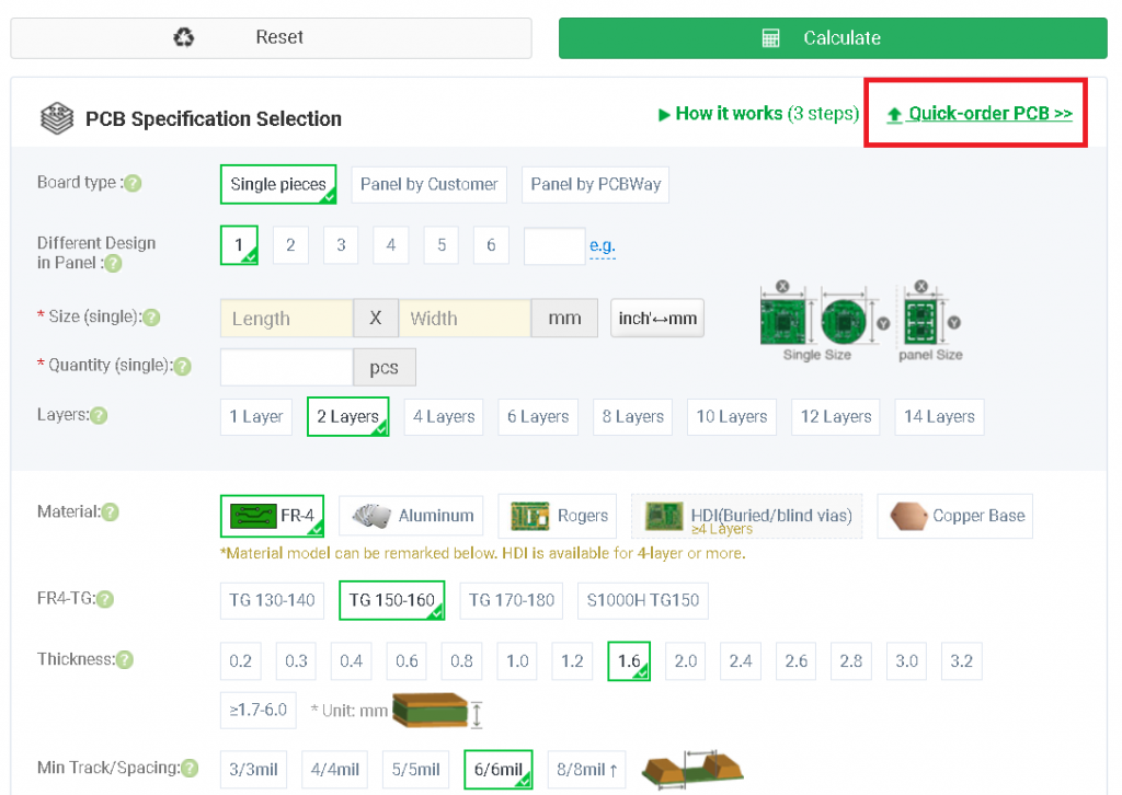
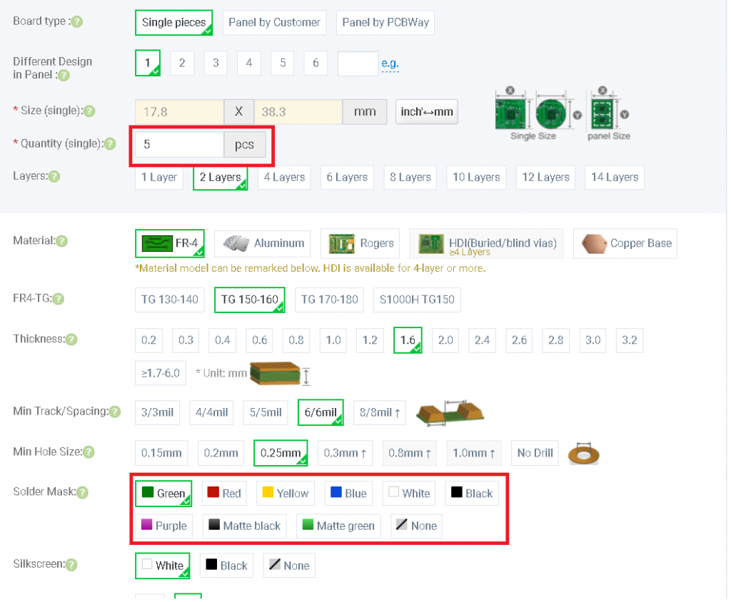
Select necessary board number and select color of boards:
Turn on assembly service, enter necessary amount of boards and click “save to cart”, after that, you’ll be requested to update BOM, Pick and Place and gerber files.
Here they are(for full assembly):
Here they are(for manual header soldering, part assembly):
Payment, shipping and delivery
PCBWay accepts ordinary debit cards, PayPal and wire transfer. It is also possible to order for a company, they provide all the necessary documents.
Shipping using E-packet takes almost one month to Europe and USA(almost everywhere)
In Europe you can pay VAT while the order and receive items with simplified customs clearance.
Soldering partly assembled boards
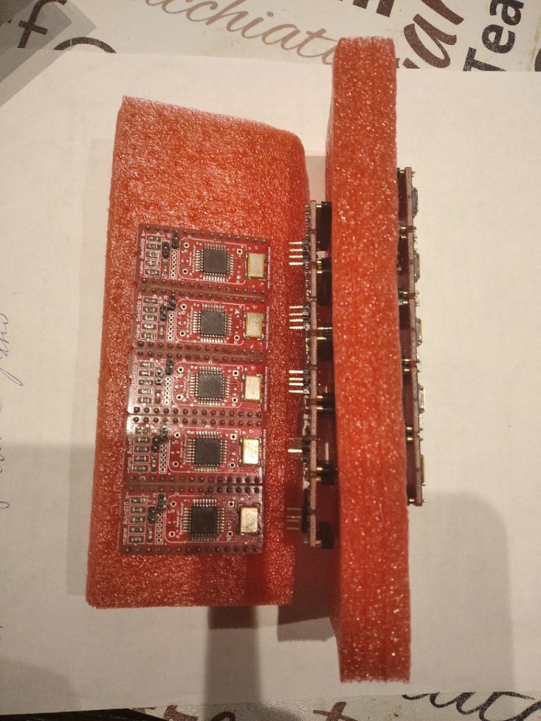
If you’ve ordered boards without DIP assembly, you’ll need 2.54 round gold-plated headers:
You can buy them here: Aliexpress headers
Flashing
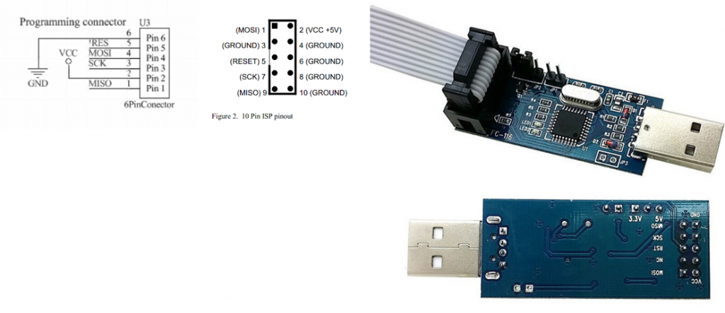
Necessary tools for flashing: USBASP Cable + adapter
Socket for USBASP: USBASP wires
Now, you need to make an adapter for flashing using USBASP.
Please connect lines 5V, MOSI, MISO, SCK, RST, GND to the corresponding pins on the bottom of USBASP.
Now, please download the flashing pack (for Windows, but you can adopt BAT file for Linux too) :
Testing
Insert to C64 socket, boot up (you’ll hear a “ping” sound)
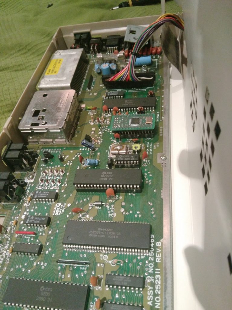
Try to load some music. If you’ve followed the instruction, you’ll hear the sound. Good luck!