Posted on Leave a comment

VW Mk1 Rabbit Instrument Cluster Pinout (9+9 Connector)

A practical engineering reference for a rare cluster variant

Overview

UPDATE: Later the official schematic was found

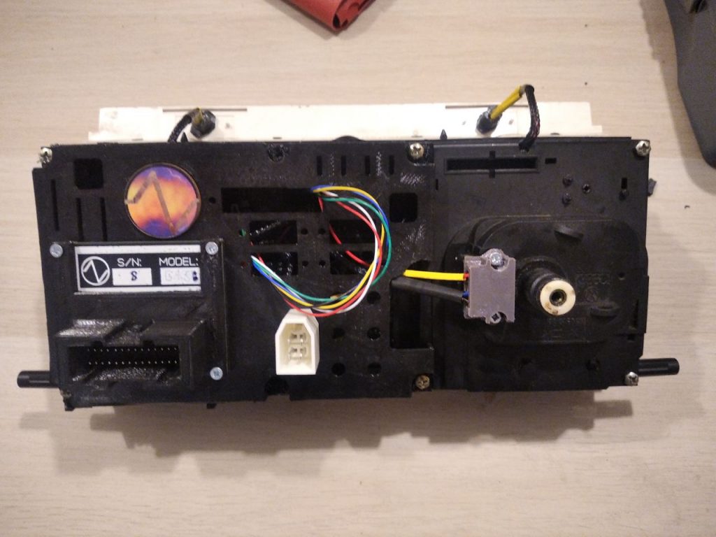
This article documents the electrical pinout and internal behavior of a rare Volkswagen Mk1 Rabbit instrument cluster for which official documentation is difficult to obtain.

The cluster uses a dual-row 18-pin connector (9+9 layout), with numbering defined from the rear side.

The main PCB is flexible (and very old) and now most of them are in very bad condition.


Connector Layout

Rear view numbering: 
1 ... 9
10 ... 18

Pinout Description

Upper Row (Pins 1–9)

PinFunctionNotes
1Not connectedElectrically linked to Pin 2 (likely missing resistor path)
2Not connectedPossibly part of unused circuit
3Constant +12VSupplies clock
4Fuel level sensorStandard resistive sender 30 – 300 Ohms (around that) – high/low.
5Tachometer input (KL1)High probability
6Illumination (KL58)Dashboard lighting
7Ground (GND)Common reference
8Not presentNo pin
9Turn signal indicatorBlinkers

Lower Row (Pins 10–18)

PinFunctionNotes
18Temperature sensorLow resistance triggers warning lamp. As usual, around 1k on amb. temperature and around 40-50 Ohms while fully heated.
16Glow plug lamp (diesel)Active low
15Oil pressure lampActive low
14PCB trace onlyRouted on board, no external function
13Seatbelt warning lampActive low
12+12V supply (likely ignition)Feeds multiple resistive paths
11Brake warning lampActive low
10Battery/alternator lampActive low, used for excitation
9High beam (KL56)+12V → lamp → ground

Internal Design Characteristics

Analog Measurement System

All primary gauges (fuel, temperature) are based on:

  • Bimetallic thermal elements
  • Heating via controlled current
  • Mechanical deflection proportional to temperature

This design is consistent with early Volkswagen clusters (Mk1, Mk2).

Stabilized Supply

  • Gauge elements are powered from a regulated ~10V supply
  • Ensures stable readings independent of battery voltage fluctuations

Indicator Logic

  • Most warning lamps operate on active-low signals
    → The cluster expects a ground signal to illuminate
  • Exceptions:
    • High beam (Pin 18) uses positive drive
    • Illumination (Pin 6) tied to vehicle lighting circuit

Notable Electrical Observations

  • No diode present in series with the alternator lamp (Pin 17)
    → Important for proper excitation circuit behavior
  • No digital electronics present (except clock but clock does not work on my unit)
    • No signal conditioning ICs
    • Tachometer input likely handled via discrete analog circuitry, but our cluster is without tacho.
  • Minimal signal processing
    → Direct wiring + passive components dominate design

Engineering Notes

  • The cluster is fully analog, making it:
    • Easy to interface with custom hardware (e.g., microcontrollers)
    • Predictable in behavior
    • Robust but less precise than modern systems
  • When interfacing:
    • Respect active-low logic for most indicators
    • Provide stable voltage for gauge emulation
    • Use appropriate signal shaping for tachometer input

Conclusion

This instrument cluster represents a classic analog automotive design, with simple yet effective circuitry. Despite the lack of official documentation, the pinout and behavior can be reliably characterized, enabling restoration, testing, or integration into custom automotive or embedded projects.

Posted on Leave a comment

Golf/Jetta 2 CE1/CE2 cluster pinout

There is a lot of unclear information about Golf/Jetta 2 pinouts so we decided to publish the information for these old cars here free of charge and so everyone can use it in projects and in repairs.

Golf 2(Jetta 2) had two generation of cars, the first was CE1 and had two sockets in the car – black and white, and the second one, CE2 – white or black single two-row 28-pin(14+14) socket with 2.54 spacing.

CE1

Below is a pinout of CE1 version of wiring with two versions of the naming.

Plugs are assembled from two parts but it’s not easy to notice it.

The plugs part number:

White:

AMP 926505+927294

Black:

AMP 926505+927293

The plugs are slightly different in their appearance.

Important – the crimped pin part number:

000979115E

It is almost impossible to buy it separately and uncrimped, unfortunately.

White connector

PinAssignment
1 (O7)Blinker output, tied to ground for the indicator lamp.
2 (A7)Frei — not connected.
3 (O6)Terminal 58, positive supply for the panel backlight.
4 (A6)Resistive coolant temperature sensor input. (1K-100 Ohm)
5 (O5)Resistive fuel level sensor input. (30-220 Ohm)
6 (A5)Ground return “For MFA”
7 (O4)Additional ground return.
8 (A4)Terminal 1 engine-speed signal (coil, distributor, or other waveform up to 12 V with possible 300 V spikes).
9 (O3)MFA mode line used to change MFA functions. (Active: connect to Car Mass/ GND)
10 (A3)UNR permanent positive supply (unused on Replica Gen One , main supply on Replica Next).
11 (B2)MFA temperature “+” lead for the ambient sensor
12 (A2)MFA oil temperature sensor lead
13 (O1)KL 56a high-beam indicator input (+12 V active).
14 (A1)Not connected

Black connector

PinAssignment
1 (O7)Terminal 15 switched +12 V from the ignition switch.
2–4 (C7, O6, C6)Not connected.
5 (O5)Handbrake indicator input (Active: connect to Car Mass/ GND)
6 (C5)KL 61 generator warning lamp drive with 120 Ω excitation resistor. (Lamp active: connect to Car Mass/ GND)
7 (O4)Oil pressure switch, 0.3 bar. (Active “failure”: connect to Car Mass/ GND)
8 (C4)Oil pressure switch, 1.8 bar. (Active “OK”: connect to Car Mass/ GND – after 3000 RPM)
9 (O3)Not used.
10 (C3)Glow-plug indicator input (+12 V active, diesel only). (Active: connect to Car Mass/ GND)
11(O2)Hall sensor input for optional speed sensors. (10V pulse output)
12 (C2)MFA block selection line. (Active: connect to Car Mass/ GND)
13 (O1)MFA reset line. (Active: connect to Car Mass/ GND)
14(C1)Free

CE2

Reference: Internal tests and checks And (many thanks):

https://www.a2resource.com/electrical/CE2cluster.html

Example connector was provided in one of the clusters, which was sourced from a car junkyard. Connector(car side) part number: 191 972 530B Additional label: “W. Germany. 6HW 16 331”

28 pin is organised by 2 rows by 14 pins. Pitch: 2.54 mm. Distance between rows: 2.54*2 mm

Cluster PinFunctionColor (A2)
01Outside Air Temperature Sensor GroundBlue/White
02Coolant Level Low (1990+ only)Violet (1989) or Red/White
03GroundBrown
04MFA Switch- ResetGray
05MFA Switch Ground, Ground for SensorsBrown/White
06MFA Switch- FunctionGreen/White
07Speed Sensor OutputViolet
08High Oil Pressure SignalYellow
09Low Oil pressure SignalRed/White
10TachometerGreen
11MFA/Clock Constant PowerRed
12Dash LightsGray
13Start/Run Power, Fuse 16Black
15MFA Switch- ModeBlack
16Battery LightBlue
17Engine Oil TemperatureBlack/White
19Outside Air Temperature SensorViolet
20Glow Plug IndicatorGreen/White
21Fuel LevelBlue
23Coolant Temperature SensorYellow/Red
24Turn Signal LightGreen
25High Beam Indicator LightBlue/White
Posted on Leave a comment

BrainBoxes GPIB: A Rare IEEE-488 Cartridge for the Commodore 64 & 128

Among the many expansion cartridges produced for the Commodore 64 and 128, IEEE-488 (GPIB) interfaces are some of the most rare. Designed to bridge Commodore’s hugely popular home computers with the professional-grade parallel bus used by PET machines and instruments, these cartridges occupied a niche market even in the early 1980s.

One of the more rare examples is the BrainBoxes GPIB cartridge. I found it one one of the websites with a lot of unrecognized stuff as HP computer cartridge 🙂 .Documentation is extremely scarce: most references found online describe a bit different BrainBoxes IEEE-488 product that uses a cartridge-like adapter connected to an external IEEE-488 interface. This board, however, is almost certainly the same design internally—just integrated directly into a single cartridge form factor.

One of the ideas will be a full recreation in KiCad, preserving this rare hardware in an open, reproducible form. Hoping to release everything on Githab soon.

Why IEEE-488 on a C64 or C128?

IEEE-488 (also known as GPIB) was widely used on Commodore PET computers and peripherals such as the 2031 series floppy drives. Later Commodore 8-bit machines switched to the slower IEC serial bus, making IEEE-488 peripherals incompatible without an adapter.

For anyone restoring or using PET-era devices – especially disk drives – the ability to connect them directly to a Commodore 64 or 128 is invaluable. This is exactly the problem solved by cartridges like the BrainBoxes GPIB.


Hardware Overview

The BrainBoxes cartridge is a straightforward but elegant design. What immediately stands out is how closely it mirrors the architecture of later IEEE-488 adapters, such as the IEC64 –with one major difference.

Core Chipset

The chipset is almost the same as on the IEC64, but instead of driving the IEEE-488 bus directly via a PIA, the BrainBoxes cartridge uses classic 75xxx IEEE-488 transceiver ICs:

  • SN75160 – IEEE-488 talker/listener bus transceiver
  • SN75161 – IEEE-488 controller transceiver
  • ROM (EPROM) – Contains the cartridge firmware
  • 74-series logic ICs – Address decoding, control logic, and signal conditioning
  • Passive components – Pull-ups, termination, and basic signal stability

This approach is much closer to traditional IEEE-488 interface designs and aligns well with how Commodore implemented GPIB in PET machines and drives.

Notice the switch for Commodore 64 and Commodore 128 ! 🙂

Design Philosophy

Using SN7516x series drivers offloads the electrical and timing requirements of the IEEE-488 bus from the CPU, making the cartridge robust and electrically compliant. While this increases chip count compared to a PIA-based solution, it results in a very “correct” GPIB implementation.

Unfortunately, SN7416X are now very rare. 5 years ago I tried to assemble PetSD device


Relationship to the IEC64 / IEC64W

If you’re interested in this topic, there is an excellent and very well-written article worth reading:

https://retrorepairsandrefurbs.com/2022/06/27/iec64w-ieee-488-parallel-interface-adapters-for-the-commodore-64-128/

That article documents the IEC64W, an adapter distributed by several German companies and since reverse-engineered and released as open hardware. While the IEC64W uses a 6821 PIA to drive the bus directly, the BrainBoxes cartridge achieves the same goal using dedicated IEEE-488 transceiver ICs instead.

Functionally, both devices solve the same problem:

  • Allowing PET-style IEEE-488 peripherals
  • To be used on Commodore 64 and 128 systems
  • Via the cartridge port, with minimal user intervention

From an engineering standpoint, the BrainBoxes design feels more “old-school GPIB,” while the IEC64W reflects a later trend toward higher integration.


Why This Cartridge Matters

The BrainBoxes GPIB cartridge is a reminder that the Commodore ecosystem was far broader than most people realize. It bridges the gap between home computing and laboratory-grade instrumentation, and it shows how third-party vendors adapted professional standards for consumer hardware.

By preserving the ROM and recreating the PCB, this cartridge can move from obscurity back into practical use -exactly where it belongs.

If you’re restoring a Commodore 2031-LP, experimenting with IEEE-488 instruments, or simply fascinated by rare expansion hardware, the BrainBoxes GPIB is a small but significant piece of retro-computing history.

Yours,

PHOL-LABS CEO

Posted on Leave a comment

Introducing the New product – Pi1541-III USB-C: A Modern Take on Pi-1541-III

Retro computing enthusiasts know the struggle—finding the right peripherals to keep their Commodore 64 experience authentic while adapting to modern power solutions. That’s why we developed the Pi1541-III USB-C, a brand-new, improved version of the Pi1541-III by tebl (https://github.com/tebl/C64-Pi1541-III).

Testing new units

Why I Designed This Enhanced Version

While working with the original Pi1541-III, I noticed a common issue: powering the Raspberry Pi efficiently. Many users rely on USB-C power adapters for their devices, but the original design primarily used a 5.5mm barrel jack for +5V power. Good quality barrel power supplies are often expensive, whereas most people already have a reliable USB-C charger at home. So, I made the decision to add USB-C support while keeping the original barrel jack for flexibility.

Developed in KiCAD: Precision and Quality

The Pi1541-III USB-C main board was entirely redesigned using KiCAD, an open-source PCB design tool. I wanted a compact, efficient, and well-optimized circuit that would be easy to assemble while maintaining the best compatibility with Raspberry Pi 3 and 4. Most of the components are SMD factory-assembled, ensuring a reliable build and reducing the effort needed for manual soldering.

Pi1541-III USB-C PCB

Key Features That Make a Difference

Pi1541-II USB-C bottom
USB-C connector and IEC, 5.5 power connector
  • Dual Power Options – Use USB-C or 5.5mm barrel jack for +5V power.
  • Plug & Play Design – Most components pre-assembled for convenience.
  • True Drive Emulation – Provides accurate cycle timing for better compatibility.
  • OLED Display & Encoder Controls – Easily browse and load disk images.
  • Supports SD Cards & USB Storage – Play your favorite C64 games effortlessly.
  • Includes an IEC Cable – No need for extra purchases.

Get Yours Today!

Pi1541
Assembled unit

The Pi1541-III USB-C is a brand-new product designed to enhance your Commodore 64 experience. If you’re looking for a reliable, modern, and easy-to-use drive emulator, this is it!

Order yours now and enjoy seamless retro gaming!

Link to the product:

(Raspberry Pi not included.)

Posted on Leave a comment

Macrosystem Vlab GAL dump

Thanks to Matze’s Galdurino (https://gitlab.com/MHeinrichs/galdurino) project I was able to dump one of GAL16V8 ICs in Macrosystem Vlab video digitizer

Galdurino and Macrosystem VLab

Before that, I connected it to my Amiga 2000 and used it to dump the picture from “composite” from A2000.

It worked OK with PiStorm(see picture)

VLab software

Here you can check Zorro II id’s of VLab:

Zorro Ids

I was able to dump Lattice GAL16V8 by applying 17V on pin 2, however STs GAL16V8S were not able to be dumped. There were other boards with the same chips by Lattice. I’ll try to take one.

And here is a dump:

https://disk.yandex.ru/d/21Gx7jowB7cb4w
Posted on Leave a comment

Firmware update of IV-Indicators temperature sensor

First indicators were sent with limited indication on temperature channel.

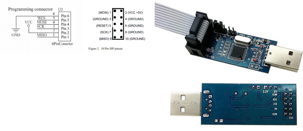
Start from connecting of indicator USB flasher according to pictures:

Please be careful as programmer can be inserted incorrectly. USB socket should be on outer side.

Next, connect programmer using USB Type-C cable to your computer (newer smartphones cables fit well)

It should be recognized as COM serial port in Windows or serial device in Linux.

Flashing is done from a Chrome browser with serial port support.

To access flashing page, go to:

https://phol-labs.com/iv

To access flasher.

Here, press select port and select appropriate serial port.

Now go to settings and check if Access Modbus setting is unchecked:

And select 115200 baud rate, if any other is selected.

Now press connect and then, press Full erase flash,

Then click “Open file” and select the firmware supplied along with this file, and press Flash. After that, device is ready for use.

Posted on Leave a comment

IV-Indicators instructions

Abstract

IV-Indicators innovative gauge offers a multitude of functions, ensuring you stay informed about crucial vehicle metrics while adding a touch of modern sophistication to your interior, and preserving retro-tech look. The killer feature of this device is that it can be configured using Android phone to fit your own sensors.

Device is shipped in 4 options:

  • IV-Indicators gauge 3xPack (all 3 indicators in one package)
  • IV-Indicators Voltmeter
  • IV-Indicators Barometer
  • IV-Indicators Thermometer

Upgrade your Golf or Jetta 2 with this versatile IV-Indicators Button Gauge, a must-have accessory for car enthusiast. This innovative gauge offers a multitude of functions, ensuring you stay informed about crucial vehicle metrics while adding a touch of modern sophistication to your interior,and preserving retro-tech look.

Package contents

Package includes:

  • Button-gauge(-s)
  • Socket for connection
  • Programming tool

Functional description

Equipped with default options to function as a voltmeter, oil pressure sensor, or temperature sensor, this gauge adapts to your specific monitoring needs with ease. Whether you’re keeping an eye on your vehicle’s electrical system, oil pressure, or engine temperature, this gauge has you covered.

What sets this gauge apart is its junction of retro and new technologies. Included with the gauge is a programmer that allows for easy configuration via your Android phone or computer using USB cable. With the ability to adjust the color of segments and backlighting, you can customize the gauge to match your vehicle’s interior or personal style effortlessly.

Not only does this gauge offer versatility and customization, but it also boasts calibration capabilities, allowing you to sync it with other sensors for precise and accurate readings. Say goodbye to guesswork and hello to confidence on the road.

Upgrade your driving experience with the Golf/Jetta 2 IV-Indicators Button Gauge and enjoy unparalleled functionality, style, and convenience.

Device is intended to be working with VAG pressure sensor p.No 03C906051A and temperature sensor Ossca 01176 or compatible for Golf 2.

Connection diagrams

IV-Conf Android pack

IV-Indicators are shipped with external programmer, which is connected as follows:

Use Type-C USB cable to connect it to your Android phone via USB-OTG. If your phone is not equipped with Type-C socket, you can use USB Hub and USB-A-USB-Type C cable.

App is in beta testing stage and is provided directly with shipped indicators.

Instructions:

Connect USB flasher to your phone and open App. Confirm and grant USB permissions to the app.

Press USB connect and wait until Connected text

On top of the app press 3 bars icon and go to Settings. Select some preset from the settings and press “Set parameters”, wait until transmission. You can also modify the settings according to your needs.

To set Dot mode, set checkbox, if use bar, leave it unpressed.

To set backlight and intensity, use the widget on the bottom of the page

To set gradient colors, select style to Gradient (default one), to select 4 color segments, select 4 segments and choose appropriate segments colors and position.

Please take in account that the app is in beta stage and will be constantly improved.

Posted on Leave a comment

Orders and website update

Website was updated and is now on .com zone.

The item number was re-stocked according to real stock. Many items were moved to “Old products”, consider contacting us if you need some of them.

The new revision of Digifiz Replica is still in development, old revision is currently(April 2024) out of stock.

A new revision of Digifiz is coming this summer.

For now take a look on our new product – multifunctional and multicolor gauges for Golf 2/Jetta 2 😀

IV-Indicators

Posted on Leave a comment

UVGEN Amiga Genlock Engineering

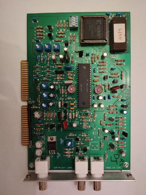
I bought this device on eBay and decided to make a replica of it.

UVGEN Genlock for Amiga

An internal genlock for the Amiga which plugs into the video slot (OCS/ECS style). This genlock appears to have been developed for use with the A2000 clone called the Sneak Prevue, a system for broadcasting programming information. The genlock was used to supply video from the Laser Disc Player. (https://bigbookofamigahardware.com/bboah/Product.aspx?id=440)

I bought this device on eBay and decided to make a replica of it. I did not found any other open source genlocks for Amiga so it would be nice to have something in this niche. 

First of all, WARNINGS:

KiCAD UVGen genlock

1) The project is completely untested. I plugged in the original card, but it is not a correct test. This project may not work at all, because there are many copper traces. 

2) UVGEN Genlock works on A2000 NTSC machines only, you need to modify circuit for PAL(and I am not sure it is possible to do that)

3) FPGA onboard has its own ROM and it was dumped. EEPROM dump is provided only for home and non-commercial usage. If you want to sell this – write your own ROM for XC2018. 

4) Of course, I am not responsible for any loss, damage, or other things caused by this project to your expensive Amiga desktop. 

5) If you successfully managed to start up this card – please tell me, if I need to do any changes in the project files. Your help will be much appreciated.

6) Inductor values should be inspired from the datasheet

UVGEN genlock consists of video overlay IC MC1378P. See its datasheet: https://pdf1.alldatasheet.com/datasheet-pdf/download/168761/MOTOROLA/MC1378P.html

This IC is controlled by FPGA with OEM ROM which makes all the necessary signals. There are also 4 switches(and thus 16 modes) of Genlock. I do not know how it works. From what I’ve seen on a screen – it chooses signals from Amiga for gen-locking and overlaying. 

HOW IT WAS USED:

UVGen connection

– To add Teletext to videos + some effects

– To add captions and credits list

– To make music videos

Original UVGEN Genlock was used for Sneak Prevue TV broadcasting system.

IDEAS ON HOW TO USE IT:

1) Make retro wave videos using composite Amiga video and other video source

2) Make original and 90s-like video clips for music

3) Output composite video from new Amiga 2000s, Amiga 2000 EATX (from jasonbeer, my respect)

I’ll share the original files within several months but first I want some orders to appear from PCBWay to generate some income from my work. Next, I’ll share original schematics and board files too. Please support my work. 

I also plan to make a small SMD-based board with the same functions.

Source and ROMs:

https://github.com/Sgw32/UVGEN_Genlock_Replica